ROOFBOX® P design guide
The Roofbox P Series brings the specifier the key benefits of:
- Off-site fabrication – pre-fabricated cabinets delivered ready-to-fit
- A modular approach for larger roof openings
- Available either to install directly over the roof aperture or onto a site formed kerb
- The option of pre-installed and pre-sealed ductwork
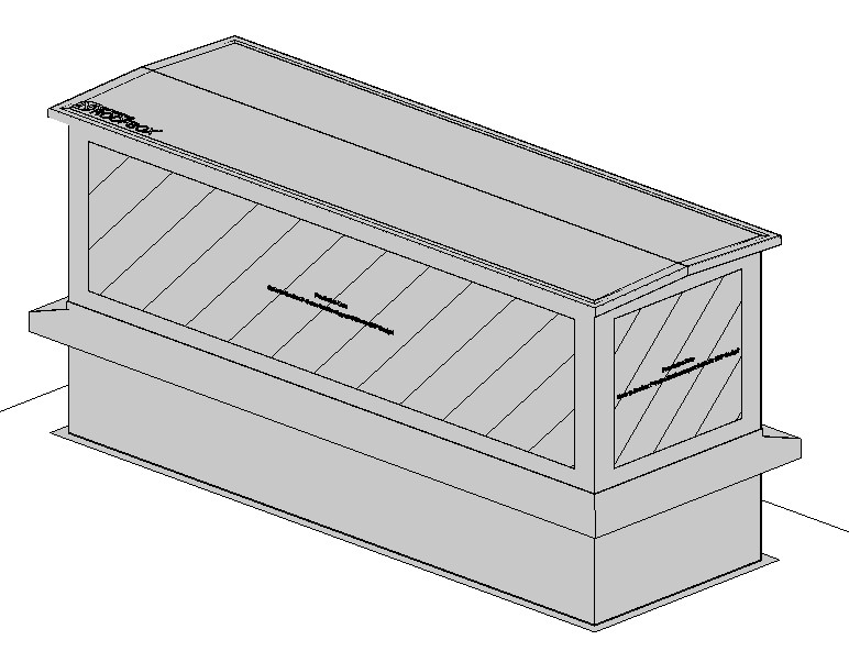
The prefabricated modular design creates a row of ‘terraced cabinets’ each with their own individual function or service within each module or cabinet whilst being consistent in height and width in any one location. Each unit is joined and sealed to its neighbour by weathering strips across the top and on each face, making it possible to provide for long roof apertures if necessary. Typically each module houses either a duct, multiple smaller services or cable tray penetrations. Rectangular and circular ductwork can be supplied pre-fitted and pre weathered into the modules. Small pipework and electrical services are normally run after the installation of the Roofbox modules using an access door for installation. The ‘P’ range is founded on the ‘sealed-in-the-factory’ approach, and the lid is not removeable. Site-fitted services can be accessed via the access hatch in the unit.
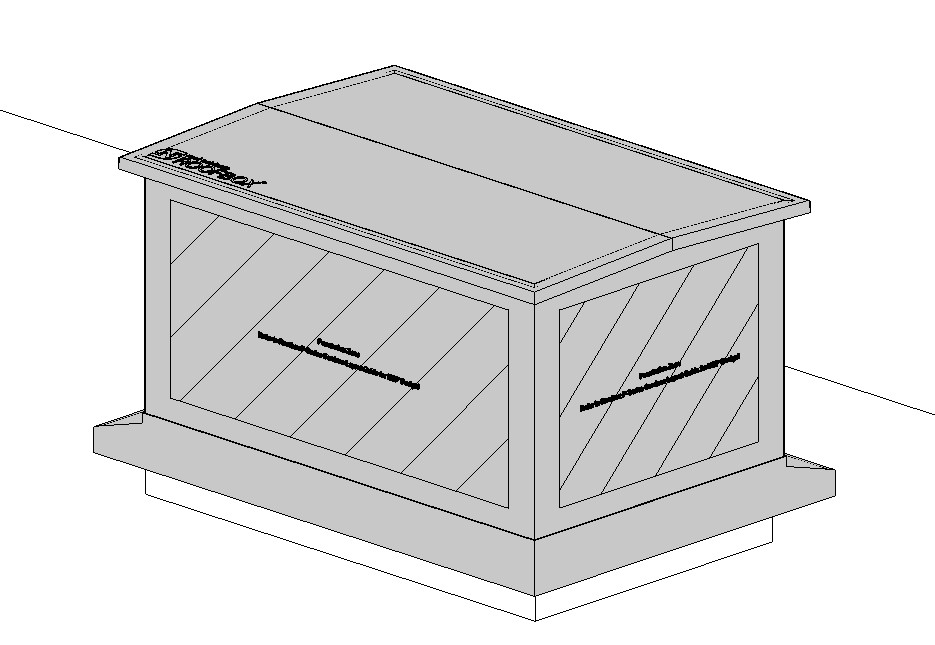
Roofbox P with an integral kerb has a downstand below the weathering apron that can be specified at a height to accommodate the depth of the roof insulation therefore eliminating the need for a site upstand to be formed. In this scenario the lower part of the Roofbox (below the apron) would have the roofing membrane weathered up and sealed to the unit under the apron. The size of this unit is determined by the roof aperture.
Roofbox P for a site formed kerb sits on top of an already formed kerb. The size of unit based is based on the external size of the structural kerb.
Using your Roofbox P Revit Families in a Project
The Roofbox P Revit family represents a set of modules for a range of services. For simplicity, a single family can be placed over each riser opening, and services run as necessary. Separate BIM objects do not need to be used for each module.
To use the Roofbox BIM Object in your project:
- Place the BIM Object on the face in your project that represents the roof level (or top-of-kerb level for the Site Kerb version)
- Size the object on plan
- For the Integral Kerb version use the required aperture dimensions. Please note that this object cuts a void at the opening size specified with the cabinet size being 100mm bigger overall
- For the Site Kerb version use the outside dimension of the kerb upstand
- Set the height of the object
- Services may then be ‘installed’ through the unit taking care to observe the following
- All services must exit through the Penetration Zone
- All ducts and single pipes must be separated by 200mm on plan where they exit the cabinet
- All services should exit perpendicularly from the cabinet
- All services should extend past the roof box by 200mm before changing direction (including bend radii)
- Services should not be stacked above one another
- Services should not exit through the cabinet roof
- Clash detection is possible by using the Roofbox Aluminium material and excluding the Penetration Zone material.


Roofbox P is designed to work with a range of duct sizes arraged square to the face of the Roofbox sides or ends. Ensure all services exit through the Penetration Zone marked on each face of the BIM model. Maintain the 200mm horizontal distance between services.
Avoid ducts and large services exiting the Roofbox at an angle, or with bends too close to that cabinet. Avoid stacking services above each other. Do not route services via the lid panel.
If you have specific requirements that need to be accommodated, please get in touch to discuss, or call us on 01763 295 828

Download the rfa files here:
Roofbox P Integral Kerb